Introduction
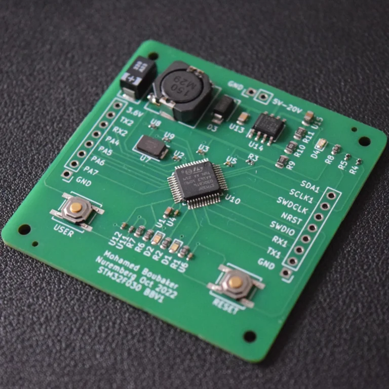
I wanted to build a custom STM32 board that I could easily program through USB. With my previous STM32 board design, I had to manually connect the wires of the ST-Link to the SWD pins of the board every time I needed to program it. You can see how that can get cumbersome very quickly.
I also wanted a battery-powered board rechargeable through USB. Having such a design in my toolbox will set the stage for designing future IoT projects that need to run in remote locations with limited power availability.
I also thought it would be useful to add an EEPROM to the design to store configuration data or any information that needs to survive a power cycle.
You can download the KiCad Project files from my GitHub Battery-Powered-STM32-Board-With-USB
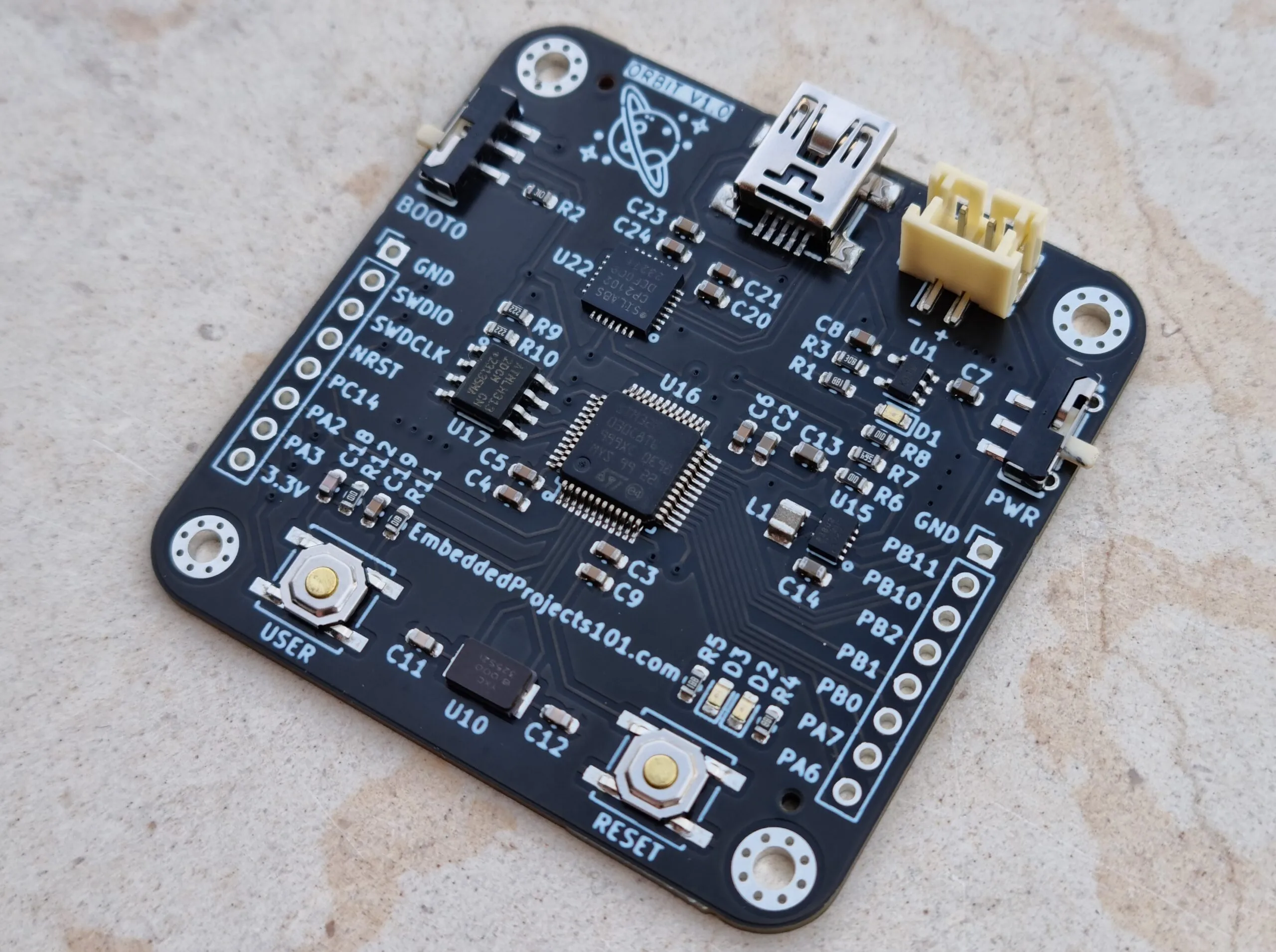
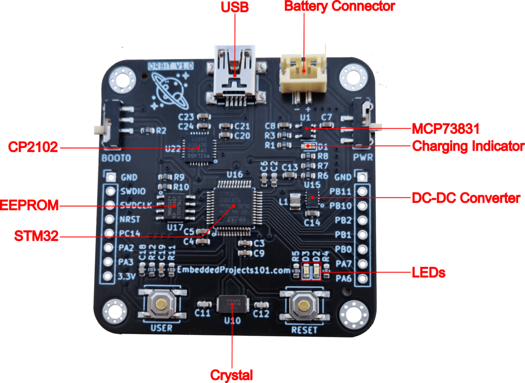
So with these requirements in mind, I ended up designing this board using the following components:
- STMicroelectronics STM32F030C8Tx MCU
- Silicon Labs CP2102 USB-to-UART
- Microchip MCP73831 battery management circuit
- Microchip ATC24C128 EEPROM
- Texas Instruments TPS63802DLAR DC-DC converter
In this blog post, I will describe the circuit of every component in this board. I will also discuss the PCB layout design and point out some bad design decisions that one should avoid.
I included all the design documents in the project’s GitHub repository. I used KiCad 7 to design this PCB and JLCPCB to manufacture it.
To get the most out of this article I recommend that you be familiar with basic electronics, reading datasheets, UART, I2C, STM32, and KiCAD.
Table of Contents
Board Design
Circuit Design
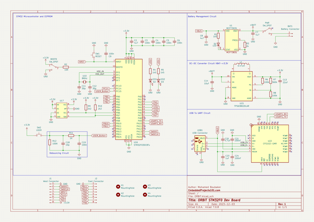
CP2102 USB-to-UART
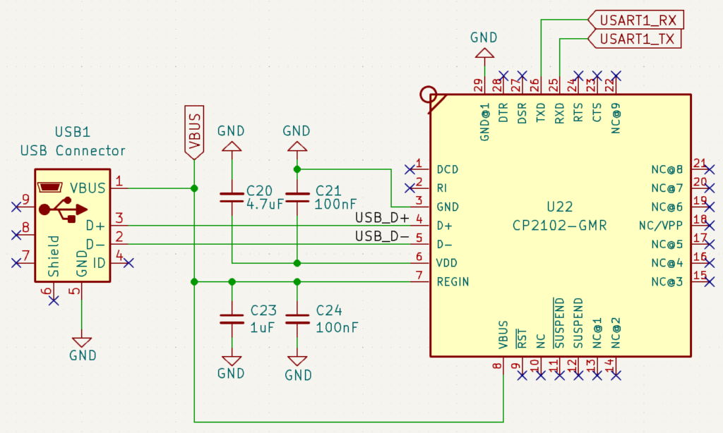
The CP2102 is a popular USB to UART chip that works with minimal external components. In fact, It only requires 4 bypass capacitors as per the CP2102 datasheet.
After installing the CP2102 Windows Driver, the PC recognizes it as a COM port. So we can use a tool like Putty to directly communicate with the UART0 port of the STM32.
The CP2102 helps eliminate the need for an external USB to UART adapter when we want to communicate with the MCU’s serial port from the PC.
More importantly, with the help of the BOOT0 pin, we can use the CP2102 USB to UART adapter to program the STM32 through UART.
USB-to-UART circuits are popular and very useful and can be found as compact dongles like the one below
MCP73831 Battery Management Circuit
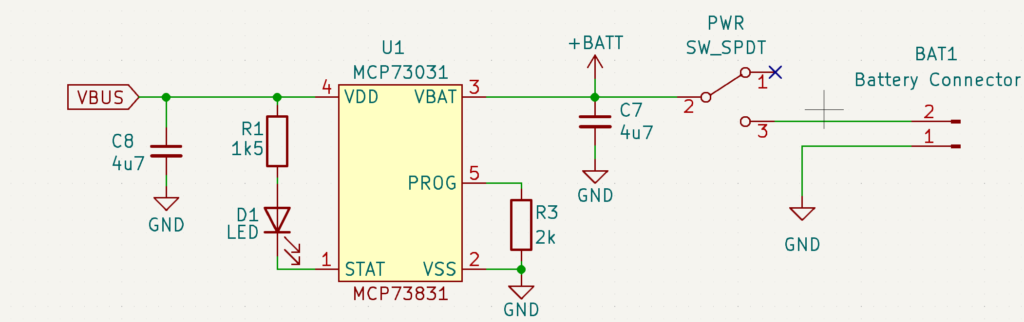
Charging a Lithium-Ion or a Lithium-Polymer battery is not as simple as hooking it up to a 5V DC source.
Charging a battery requires applying a voltage that is a just little higher than the battery’s current voltage and then gradually increasing the voltage while maintaining a constant current until the battery reaches its maximum voltage which is typically 4.2V for a Li-Ion cell.
A battery management circuit such as the Microchip MCP73831 will take care of charging the battery using the 5V power provided by USB (VBUS).
The MCP73831 is simple to use. The STAT pin is an output for connection to an LED that indicates the charging status. When the battery is fully charged, the LED will turn off.
Using a resistor connected to the PROG pin, we can configure the maximum charging current, which governs the charging duration.
The MCP73831 datasheet provides the formula for relating the PROG resistor to the charging current which can vary between 15 mA and 500 mA.
There are many Lithium-Ion or a Lithium-Polymer options with different capacities that can be used to power this board. I used the one below
TPS63802DLAR DC-DC Converter
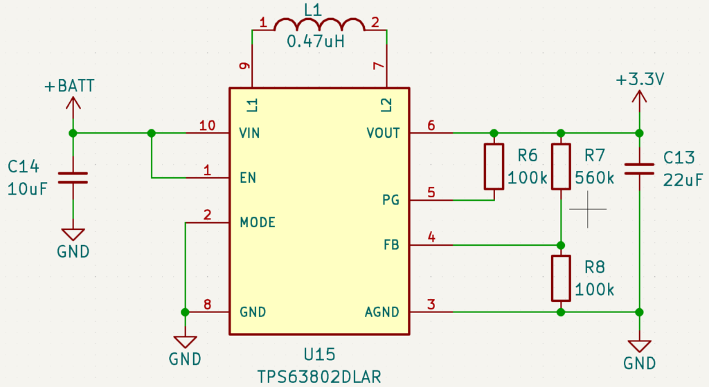
The typical voltage of Lithium-Ion batteries is between 3,7V and 4.2V, while the maximum acceptable voltage of the STM32 MCU is 3.6V, therefore we need a converter to bring the voltage down to 3.3V.
The TPS63802 has an input voltage range between 1.3V and 5.5V, so it is suitable for converting the battery voltage into 3.3V for the MCU, EEPROM, and the rest of the board.
STM32F030 MCU
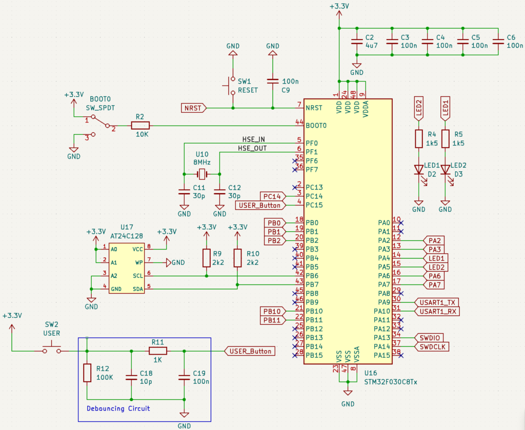
The STM32F030C8T6 is cheap, around 0.7$, and offers all the essential peripherals required for this board. It features:
- ARM Cortex-M0
- 2.4V~3.6V operating voltage
- 4MHz~48MHz clock speed
- 64KB Flash memory
- 8KB SRAM
- 2 USART, 2 I2C and 2 SPI.
- 7 Timers
- 1 ADC
AT24C128 EEPROM
EEPROMs are useful to hold data that must be retained after a power cycle such as configuration data or serial numbers.
The STM32 communicates with the EEPROM via the I2C bus which is composed of the SDA (PB7) and SCL (PB6) lines.
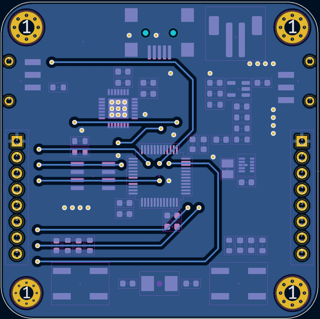
PCB Layout
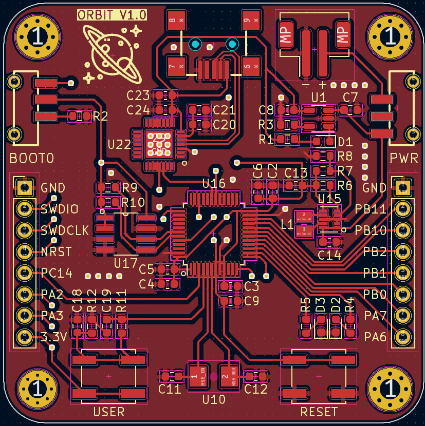
The signals on this board are relatively low. We have I2C, UART, and USB at 12 Mbps. So we get away without paying a lot of attention to signal integrity issues.
Routing USB is the most interesting part. USB signals D+ and D- are a differential pair so they should be routed together. Additionally, USB signal trace impedance must be controlled at 90 ohms.
However, the CP2102 supports USB 1.1 Standard which runs at 12Mbps which means we can mess up the impedance and still get away with it.
Here is a great article from Altium Academy Routing Requirements for USB 2.0 which compares the signal propagation delay on the board to the signal’s rise time and derives the rule of thumb that we followed.
As long as the distance between the USB connector and the USB chip is less than 10% of the distance traveled by the signal during the rise time, then impedance matching is not critical.
Layout Flaws
After finishing the design I asked the community on subreddit r/PCBCircuitDesign to give me feedback about the layout and to point out any issues that existed.
I got a lot of really good comments. I learned a lot from their feedback, here are the most important points:
- The bypass capacitors don’t have GND vias nearby. This means, in certain cases, the return current path between the GND pin of the capacitor and the GND pin of the MCU is relatively longer, making the placement of bypass capacitors futile.
The best practice to follow here is to make sure that the bypass capacitor GND and the MCU GND are connected within the shortest distance possible, which means employing vias when necessary. - The Crystal is not close enough to the STM32. I put the crystal a little far for aesthetic reasons, I wanted the crystal to be in line with the push buttons, but the community did not like it.
Placing the crystal is vital to ensure the correct functioning of the MCU. Here is a great application note from ST about crystal circuits AN2867 Oscillator Design Guide for STM32 MCUs - Traces connecting PA2 and PA3 to the side connectors cross the crystal traces from the lowerside of the PCB.
This would have been bad for signal integrity if PA2 and PA3 carried high-frequency signals. Fortunately, these traces only carry USART2 signal which is limited to some Khz.
But as a rule of thumb, never cross a high and analog high-frequency trace with a digital signal carrying a trace - Stitching Vias were missing, if you don’t know what’s that, here is Everything You Need To Know About Stitching Vias an article from Altium.
I routed some traces on the GND plane which interrupted the GND plane without adding stitching vias. This can lead to excessive EMI propagation.
The board works even with these issues. These issues will not lead to problems for low-frequency signals, however, if this design were to run at a higher frequency, problems will start to appear.
It is always good to follow battle-tested design guidelines to avoid unnecessary troubleshooting and redesigns,
By the way, the Kicad project files available for download include all the improvements suggested by the community.
Don’t Miss The Upcoming Projects!
Sign up to the newsletter to get notified whenever a new Project or Tutorial is published.
You can unsubscribe anytime.