I include links to products I think could be useful for my readers. As an Amazon Associate, I earn commission from qualifying purchases.
Introduction
Project Overview
This project aims to deliver a custom GPS tracker that can be used mainly to track a vehicle. The system includes a device that periodically sends its position and speed information to a remote server. The data is stored on the server where it can be accessed through a web browser for visualization.
The scope of the project is focused on the embedded side. In other words, the development of the server and visualization platform are not mature. However, this work is mainly concerned with designing a circuit, manufacturing the PCB, and developing firmware to power it, all while ensuring reliability.
Quick Links:
GitHub Project Repository
Table of Contents
Toolchain
- Development boards: STM32F0 Discovery and SIM808 EVB-v3.2.4
- MCU Configuration: STMCubeMX
- IDE: STM32CubeIDE v1.10.1
- Compiler: arm-none-eabi-gcc
- Flashing utilities: STM32 ST-LINK Utility and ST-link programmer
- PCB Design: KiCAD version 6
- PCB Manufacturing: JLCPCB
Project Phases
The realization of this project was divided into 3 main phases.
The first phase of the project involved selecting the Microcontroller (MCU) and GPS/GPRS module, and then designing a minimalistic Proof Of Concept (POC) using development boards.
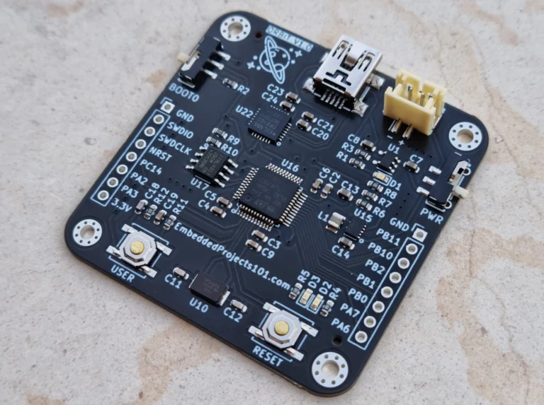
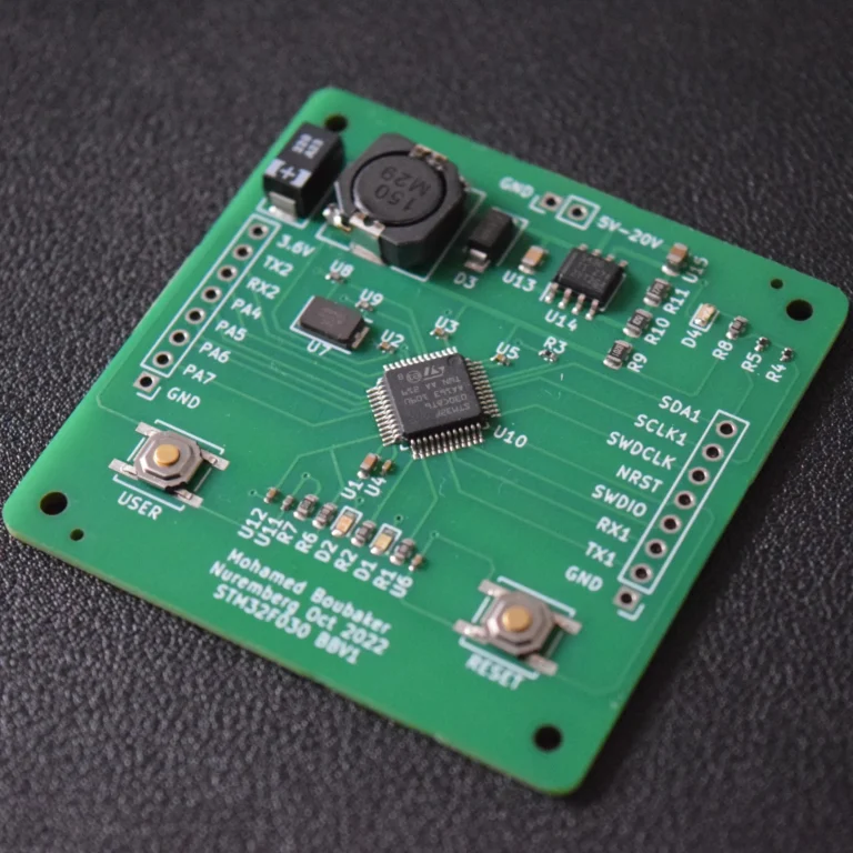
You can also build this project using bare development boards like the ones below instead of making a custom PCB.
The second phase involved designing the circuit and PCB. After the hardware design phase was completed, PCB prototypes were ordered from JLCPCB. This phase also included designing and ordering a POC PCB that includes only the power regulation circuit and MCU. This effort resulted in a stand-alone custom STM32 development board.
In the third phase, the firmware that was initially developed during the POC stage was further refined to fit the new custom PCB and enhanced to become more reliable.
System Design
System Architecture
The system is composed of 3 main parts: a PCB, firmware, and a server.
- The PCB circuit contains 3 major elements:
- A power regulation circuit based on the Texas Instruments TPS5430DDA DC-DC down converter, which is configured to safely convert any voltage between 5.5V and 20V to 3.6V.
- A GPS/GPRS module: SIM808, which is capable of receiving GPS signals and also connecting to a GPRS network, which means connecting to the internet.
- This module relies on a GPS tracker sim card plan which is a sim card for GPS tracking and other IoT applications from the provider thingsmobile.com which has coverage in many countries and can be considered as a cheap sim card for a GPS tracker.
- An STM32 MCU: STM32F030, which is the brains of the PCB. It controls the SIM808 module via UART.
- The firmware is composed of 4 main source files:
- sim808.c contains the functions to startup, reset and send commands to the SIM808 module.
- gps.c contains functions to enable/disable GPS functionality and get GPS position and speed information.
- network_functions.c contains functions to set up GPRS, send raw data through a TCP session, and publish messages to an MQTT Broker.
- aes_encryption.c contains an implementation of the AES-128 encryption algorithm. It is used to encrypt the MQTT messages before sending them to the server.
- The server, which is an EC2 instance that has the following services running:
- Mosquitto MQTT Broker, which is used to receive messages from the remote GPS boards.
- An MQTT subscriber, which is a python script running as a systemd daemon responsible for processing all incoming messages to the broker and saving the Board ID, position, speed and time stamp to a database.
- An SQL database which is PostgreSQL used to store the position data of the boards.
- A web application utilizing Angular and Spring Boot, hosted on Apache HTTP Server, used to display the historical location of the device on a map.

Firmware Design
The code is developed to serve as GPS tracker API for AT-cmd-enabled GPS modules. It features Doxygen-style documentation for all functions, providing clear explanations of their operations. This documentation has been compiled and can be accessed at the following link Code documentation
The implementation details of the AES encryption algorithm are described in a separate repository here.
Circuit Design
Circuit Schematic
TPS5430DDA DC-DC Down Converter
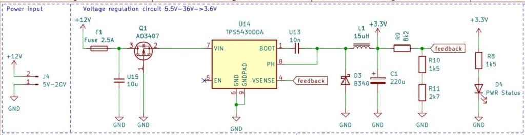
The voltage regulation circuit is designed to achieve the following goals:
- Be tolerant to reverse polarity.
- Protect the circuit in case of a short circuit.
- Be able to withstand input voltages that are typical of a car battery. i.e. 12V~20V.
- Provide peak currents of up to 2A. This is required by the SIM808 module. [2].
- Provide a stable output voltage of 3.6V because the operating voltage range of the STM32F0 MCU is 1.8V-3.6V [3] and that of the SIM808 module is 3.4V-4.4V [2] .
Reverse polarity protection is achieved through the MOSFET transistor denoted as Q1 in the schematic above which has a Gate-Source voltage rating of 20V. This limits the maximum input voltage of the circuit to 20V.
Protection against short circuits is provided through the Fuse denoted as F1 with a rating of 2.5A. (In practice, 2.5 A is a very high current for such a circuit. If a short circuit happens, many components would fail before the fuse breaks the current. This value needs to be reconsidered.)
The rest of the requirements are met using the Texas Instruments TPS5430DDA DC-DC down converter. The components on the right side of TPS5430DDA in the schematic are designed according to the recommendations of the datasheet [1].
The output voltage is determined by the values of the resistors that are connected above and below the feedback point (see the schematic above). In the datasheet, the resistor above the feedback point is denoted as R1, whereas that below the feedback point is denoted as R2. According to equation (12) in the datasheet the following formula can be derived:
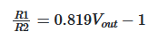
Therefore, to achieve a regulated voltage of 3.6V, the ratio between the resistors should be as follows:

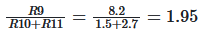
It is difficult to achieve that ratio using 2 standard resistor values, for example, 220Ω, 1kΩ or 2.2kΩ. So as a solution, R2 can be replaced by 2 standard value resistors in series. Hence the placement of 2 resistors in the circuit design, which are R10 and R11 which are equivalent to R2 in the datasheet. R9 in the design is equivalent to R1 in the datasheet.
To achieve a ratio of 1.95, i.e. an output voltage of 3.6V the following values can be used. R9=8.2kΩ, R10=1.5kΩ and R11=2.7kΩ. Below is the equation to demonstrate this:
SIM808 GPS/GPRS Module
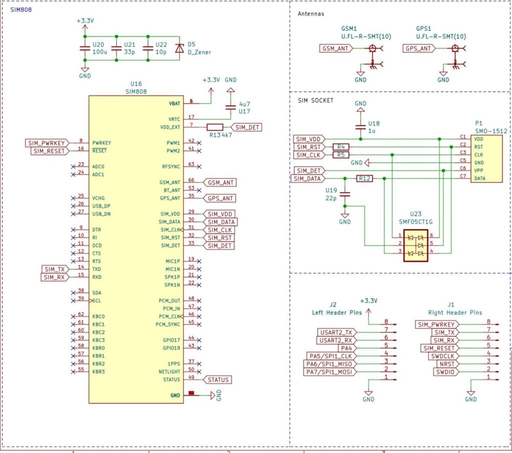
The circuit design for the SIM808 module followed the guidelines in the SIM808 hardware design guide [2] . Bypass capacitors U20, U21, and U22 were added as recommended. The guide also suggested using a 5.1V Zener diode (D5) to protect against voltage surges. Although the diode was added as per the guidelines, it caused the circuit to malfunction after powering on, so it was manually desoldered.
The SIM808 module is connected to a micro SIM card holder. The lines between the module and the holder are protected against voltage surges using Transient Voltage Surpression (TVS) diodes present in the integrated circuit U23. Capacitors U18, U19 and Resistors R4,R5 and R12 are recommended by the guide.
The GPS and GPRS antenna outputs are connected to 2 U.FL connectors respectively.
The SIM808 module and the STM32 MCU communicate using UART. The STM32 can also power on, reset, and check the status of the module through its GPIO pins which are connected SIM_PWRKEY, SIM_RESET and STATUS pins on the module. These SIM808 pins including the UART are also exposed through the header pins connector on the PCB. Which enables controlling and communicating with the module from the outside, without having to write a program to do so on the STM32.
STM32F0 Microcontroller
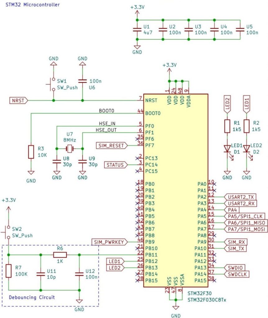
The STM32 is connected to a Reset and a User button, and 2 LEDs: D1 and D2. The User button SW2 is surrounded by a typical debouncing circuit which is inspired by the debouncing circuit found on the STM32F4 Discovery board.
An 8MHz Crystal is used to synchronize the MCU’s clock. U1, U2, U3, U4 and U5 are bypass capacitors added as per the recommendations in the datasheet [3].
SWD pins, required for programming the MCU, and several other GPIOs are exposed through header pins on the PCB. This enables the functionality of the board to be expanded. For example, it can be connected to external sensors and actuators.
PCB Design
Below is a 3D picture of the manufactured PCB. The front side is on the left and contains mainly the TPS5430DDA Power regulation circuit on top and the STM32F0 in the center. On the right you see the PCB’s backside which contains the SIM808 and SIM card holder circuit.
Design Flaws
After receiving the board and performing initial tests it turned out that this design suffers from 2 main issues:
Zener Diode Issue
In some received boards, Zener Diode D5 which is recommended by the hardware design guide of the SIM808 module, got damaged and short-circuited which prevented the PCB from correct power on.
The solution is to manually desolder and remove the Zener Diode. The reason for the damage is not known, it could be that heat from the soldering process damaged the Diode.
Antenna Power Issue
The GPS antenna signal line lacks a DC bias, preventing it from functioning correctly.
The received GPS signal is typically in the order of -125 dBm, in typical GPS devices an active antenna is usually necessary. An active antenna requires power to turn on the low noise amplifier (LNA) circuit that comes with it.
This design lacks the capability of injecting power into the GPS signal line.
The solution is to manually inject power into the GPS antenna trace and make sure it goes only to the antenna and not to the SIM808 GPS signal input. Such a circuit is known as a bias tee. In this case, an external Bias-tee can be used as a workaround.
Results and Evaluation
Test Drive
The test drive depicted on the map below was carried out from Nuremberg to Munich on board the ICE train which reaches speeds of 300 km/h. The blue line represents the path that the GPS tracker traveled. The covered distance was around 170Km and the trip was around 1h30 of duration.
The GPS board update frequency for this test was programmed to around 3 times/seconds which resulted in around 1500 position points uploaded to the server which can be examined in this file.
During the trip the GPRS connection suffered 3 times a sudden disruption, but the board rebooted automatically and recovered the connection.
Conclusion
In conclusion, the objective of this project was to design and develop a GPS tracking system. The system comprises a custom-designed PCB board, firmware running on an STM32, and a server for collecting and visualizing data. The PCB board includes a power regulation circuit, GPS/GPRS module, and an STM32 MCU. The firmware includes code to control the SIM808 module and extract GPS and speed information. The server comprises an MQTT broker, an MQTT subscriber, an SQL database, and a web application to display the device’s location on a map.
The project went through a prototyping phase, circuit design, PCB layout design, and firmware development. Finally, the system was tested on an ICE train, traveling at a maximum speed of 300km/h, from Nuremberg to Munich, and the results demonstrated the reliability of the device.
Don’t Miss The Upcoming Projects!
Sign up to the newsletter to get notified whenever a new Project or Tutorial is published.
You can unsubscribe anytime.
Hi Mohamed Boubaker! Thanks for the article, very interesting! The article doesn’t describe much at all about the server side of the project as well as its web application. If possible, I would like to know more about the server setup, database and the web application itself. I would be grateful for a reply!
Hi Alex, Thanks for your comment, unfortunately, the server/database implementation was never fully finished, that’s why I did not describe it in this article.
However, I am working on a new version of this GPS tracker that I will publish soon in a new article, I will include the documentation for the server/database side. I hope it will be useful.
Woow muhammad this is one of the best tutorials in all internet thanks you so much for sharing this my friend. God bless you