I include links to products I think could be useful for my readers. As an Amazon Associate, I earn commission from qualifying purchases.
Introduction
Table of Contents
The conventional way to program an STM32 is to use an ST-Link or another Serial Wire Debug (SWD) programmer. However, it is also possible to flash the STM32 without a programmer using one of its serial interfaces, such as UART, I2C, or USB, etc.
In this tutorial, I will explain how to program an STM32 via UART. First, I will cover some important concepts, such as the different boot modes and how to switch between them and the STM32 factory Bootloader.
I will discuss some of the Cortex M0 processor’s deep-level details, but if you just want a practical answer, jump to the last section.
In the last section, I will present the steps to program the STM32 using ST’s latest flashing utility STM32Cubeprogrammer and USB-to-UART adapter like this one below
What Are Boot Modes
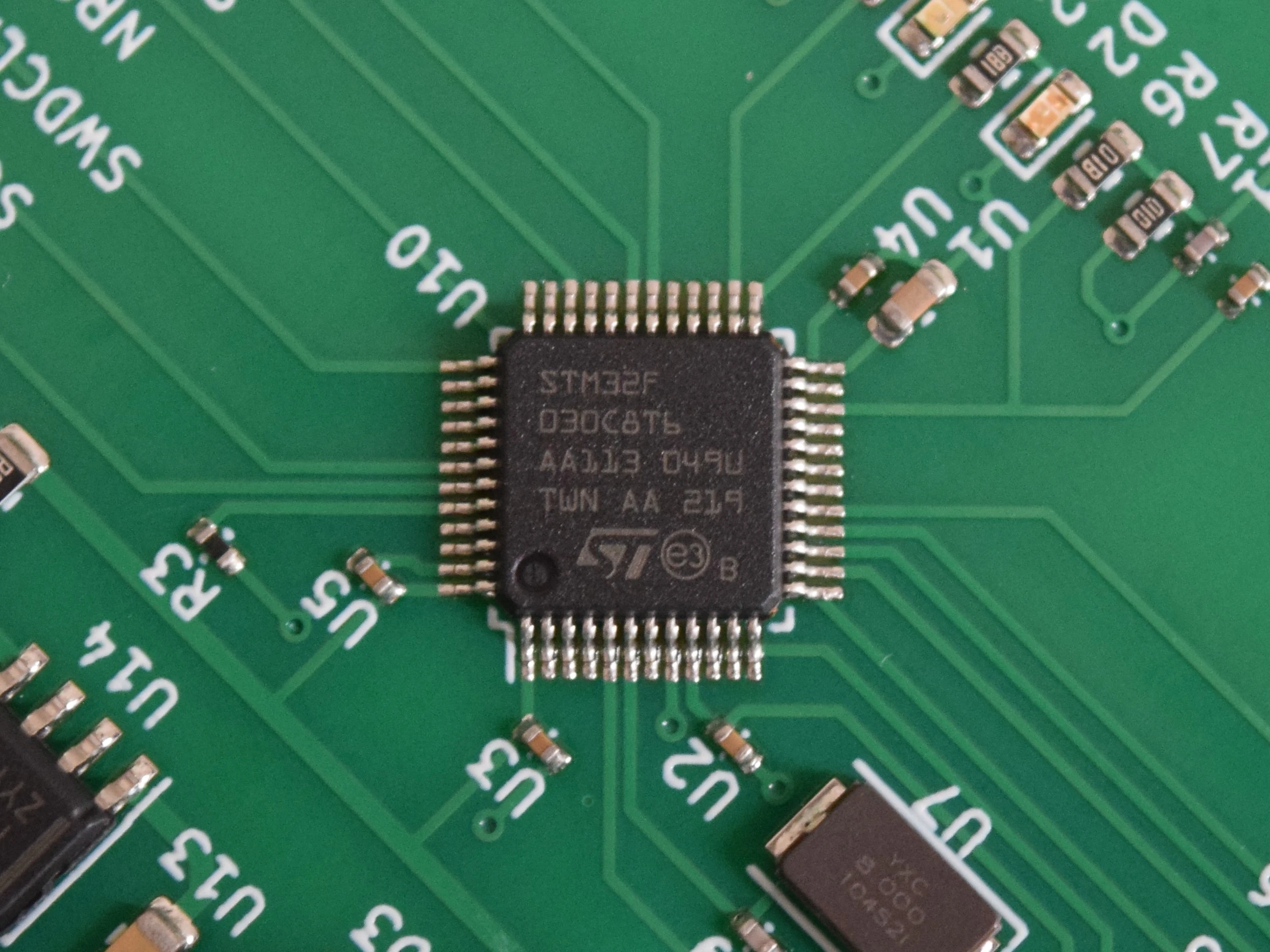
I will use the STM32F030x8 microcontroller as an example to discuss boot modes. The principles discussed apply similarly to other STM32 microcontrollers.
The STM32F030x8 is powered by the ARM Cortex M0 processor. At startup, this CPU always reads what’s stored in memory address 0x0000_0004 because it includes a pointer to the first instruction that it will execute.
In the STM32F030x8, the address space 0x0000 0000 – 0x0000 7FFF is remapped to a different area of memory. It can be mapped to the main Flash memory starting at 0x800_0000, to the System memory starting at 0x1FFF_EC00, or to the SRAM starting at 0x2000_0000.
This means reading or writing to 0x0000 0000 – 0x0000 7FFF0 space is redirected to the address space starting at 0x800_0000, 0x1FFF_EC00, or 0x2000_0000.
If the address space 0x0000 0000 – 0x0000 7FFF is remapped to the main Flash memory starting at 0x800_0000, then reading from address 0x0000_0004 is actually reading from 0x800_0004.
This means that at startup, the Cortex M0 will execute the instruction pointed by address 0x8000_0004, so the CPU will execute the program stored in the main Flash memory.
If the address space 0x0000 0000 – 0x0000 7FFF is remapped to the system memory starting at 0x1FFF_EC00, then the program stored in System memory will be executed at start-up and not the program in Flash memory.
The same is true for SRAM if the address space 0x0000 0000 – 0x0000 7FFF is configured to mirror SRAM space.
Boot Mode refers to starting the program execution from Main Flash, System Memory, or SRAM.
The Figure below is taken from the STM32F030x reference manual showing the memory map. I marked in a red box the address space 0x0000 0000 – 0x0000 7FFF0. Note that it says Flash, system memory, or SRAM, depending on the BOOT configuration.
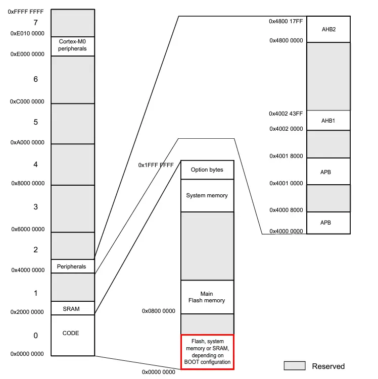
The exact memory map is different for each STM32 model. Check the reference manual of your STM32 to find the exact memory mapping.
How To Configure Boot Modes
For the STM32F030x, selecting the boot mode is configured using 2 variables: BOOT0 and nBOOT1. The BOOT0 value is sampled at start-up from the BOOT0 Pin.
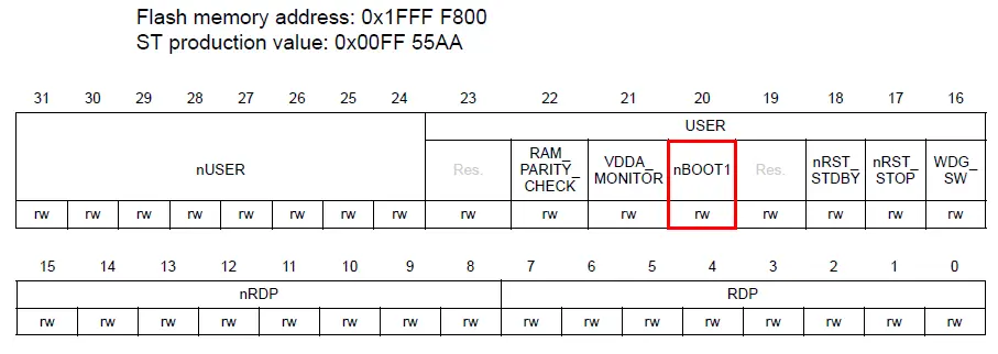
However, nBOOT1 is a register bit and not sampled from a pin. It is bit number 20 of the “User And Read Protection Register” mapped on memory address 0x1FFF_F800 and assigned a default value of 0x00FF_55AA.
Depending on the sampled values of these 2 variables, the STM32F030x maps the first section of memory to the main Flash memory, System memory, or SRAM leading to a boot from a different memory area.
| nBOOT1 | BOOT0 | Boot area |
| x | 0 | Main Flash memory is selected |
| 1 | 1 | System memory is selected |
| 0 | 1 | SRAM is selected |
By default, the nBOOT1 bit is set to 1 because the initial value of the User and Read Protection Register is 0x00FF_55AA
So, if BOOT0 is set to 0, then the program in the main Flash memory is executed at startup. If, however, BOOT0 is set to 1, then the program stored in System memory is executed at startup. Changing the value of BOOT0 is done by connecting the BOOT0 pin to GND or VCC.
Your program is stored in the main Flash memory. System memory, on the other hand, is a special memory area that contains, among other things, a different program called a Bootloader which is programmed into the MCU during manufacturing.
What is the STM32 Bootloader
The Bootloader is a program that comes preloaded in the MCU’s System Memory. It helps program the STM32’s main Flash memory through serial interfaces like UART, I2C, USB, etc.
The STM32F030x8 Bootloader only supports programming through UART. Other STMs like STM32F070x6 support programming through UART, I2C, and USB.
When the STM32F030x8 enters Bootloader mode, meaning when Bootloader is executed, it enters a loop and keeps waiting to receive predetermined commands through one of the serial interfaces as described in the figure below.
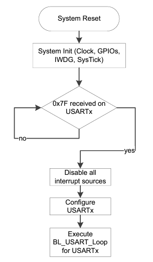
There are many Bootloader commands, such as GET Version, GET ID, Read Memory, Write Memory, etc. These commands and their behavior could slightly change depending on the Bootloader version. You can learn about them in ST’s Application Note AN3155 USART protocol used in the STM32 bootloader.
So, to program the STM32 via UART, you have to enter into Bootloader mode, send the right commands via UART, and then send the program binary. Eventually, the Bootloader will program your binary into the main Flash memory.
Luckily, the STM32CubeProgrammer knows which commands to send to the STM32 through UART, so you don’t have to worry about it.
Steps To Program The Main Flash Memory via UART
Make sure you installed STM32Cubeprogrammer and you have a working USB-to-UART adapter like this one
- Connect your USB-to-UART adapter to the STM32 UART pins.
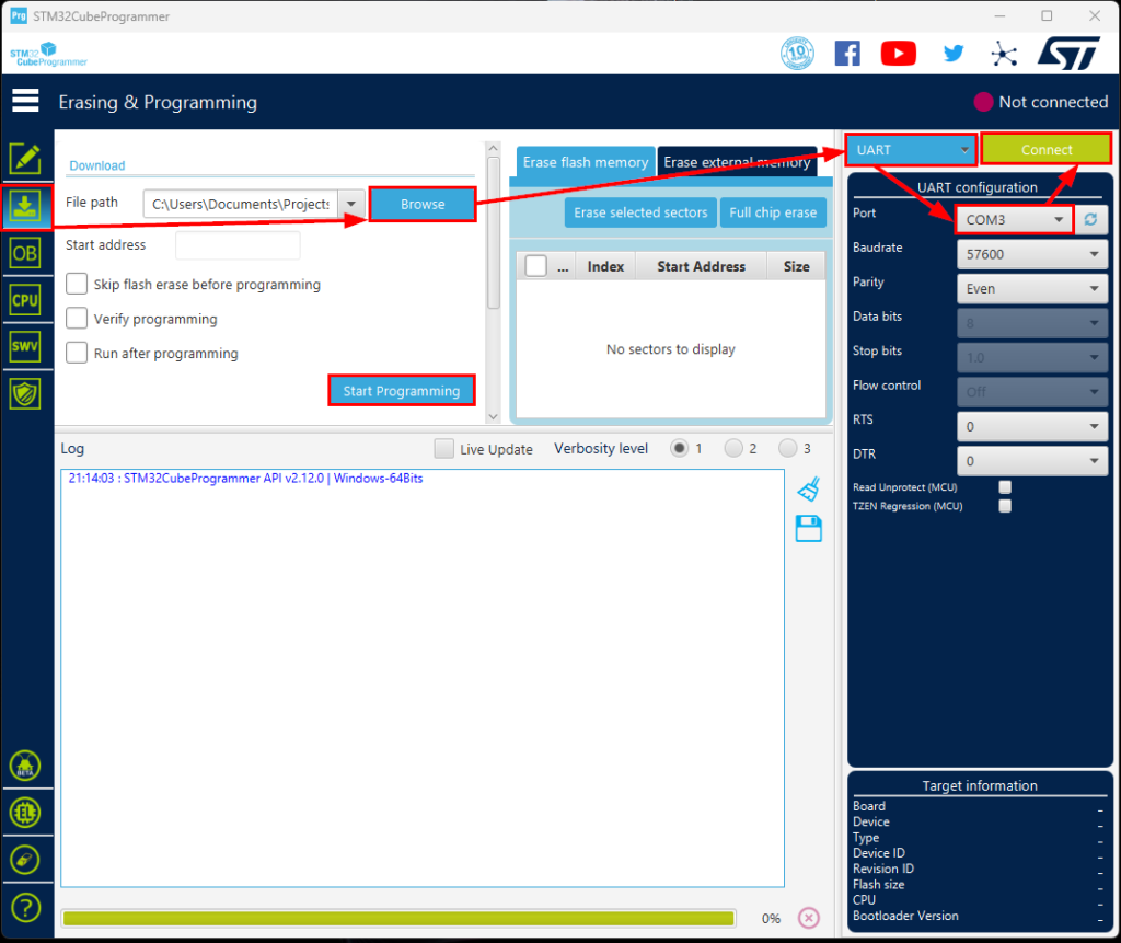
- Launch STM32CubeProgrammer; on the left pane, click the second icon, “Erasing and programming”.
- In the middle, under the download section, click Browse and navigate to your program binary (.hex file).
- On the right pane, choose UART instead of ST-LINK.
- Choose the COM device corresponding to your USB-to-UART adapter.
- Configure your STM32 to boot from System Memory. You can find out how from your STM32’s reference manual section “Boot Configuration”. For example:
For STM32F0x0, this is done by pulling the BOOT0 pin to VCC.
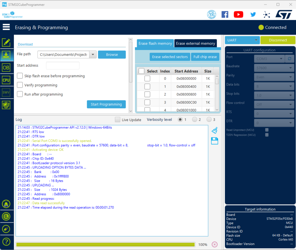
For STM32F4xx, this is done by pulling the BOOT0 pin to VCC and pulling BOOT1 to GND. - Click connect and quickly reset your STM32 by pressing any available reset button on the board or momentarily pulling the NRST pin to GND.
- At this point, you should see in the logs that the STM32 is successfully connected and some data, such as the Chip ID and Bootloader protocol version.
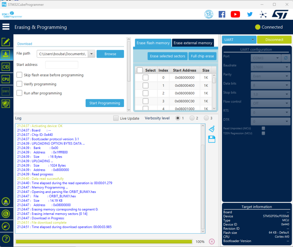
- Click on Start Programming and wait a few moments till the program is loaded into the MCU’s Flash.
- Reconfigure the STM32 to boot from the Flash memory.
For STM32F0x0, this is done by pulling the BOOT0 pin to GND
For STM32F4xx, this is done by pulling the BOOT0 pin to GND regardless of the BOOT1 pin value.
If you forget this step, if you reset your STM32, you will end up again in Bootloader mode. - Reset your STM32. Now, It should execute your new program.
.
Conclusion
Although we can program STM32s using an ST-Link or a different SWD programmer, in certain situations, it is more convenient to program them using UART. An example would be batch programming of multiple boards.
In this article, we discussed what are the STM32 Boot Modes and how they are implemented on the STM32F030x series, what’s a Bootloader and how to use STM32CubeProgrammer to flash an STM32 using UART.
Don’t Miss The Upcoming Projects!
Sign up to the newsletter to get notified whenever a new Project or Tutorial is published.
You can unsubscribe anytime.